Resistive level measurement
LR
- Continuus Level Monitors
- Float Level Monitors(continuous or step signal output)
Main application
Pressure vessels or chemical tanks such as hydraulic acid or sulfuric acid.

Main feature
Insensitive to process conditions such as pressure, temperature and specific gravity.
Versatile and easy-to-use controller. (MP2000)
Analog output (2 wire, 4 to 20mA DC) available as standard.
Principle of Operation
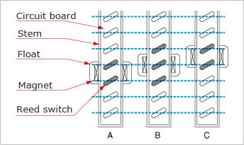
LR is comprised of a float and a stem. The float has a magnet inside. The stem incorporates a circuit board with reed switches and resistors placed at regular intervals.
For a rising level, float location and reed switches in operation change as shown in Fig.1, from A(2 switches in operation) to B (3 switches in operation), and then to C (2 switches in operation). For a falling level, from C to B, then to A.
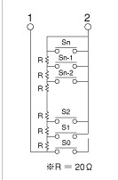
This means that the combined resistance changes as the float rises or falls. When constant current is applied to terminals 1 and 2 in Fig.2, a voltage proportional to the combined resistance is gained on these terminals.

Fig. 1: Operation of float and reed switches

Fig. 2: Circuit in the stem

